Muamp development from the start
Muamp started with an initial aim to design and build an ideal headphone that provides ultimate sound reproduction.
If you have any questions/comments, I can be contacted by email, using the email address given on the 'About us' page. I am also an active member of 'Head-Fi.org' on the DIY forums. You can PM me at 'Head-Fi', user name 'Muamp'.
This is a selection of photos shown in chronological order from the start showing the development of the headphones.
New photos are now added to the top of the page. Going down the page goes back in time.
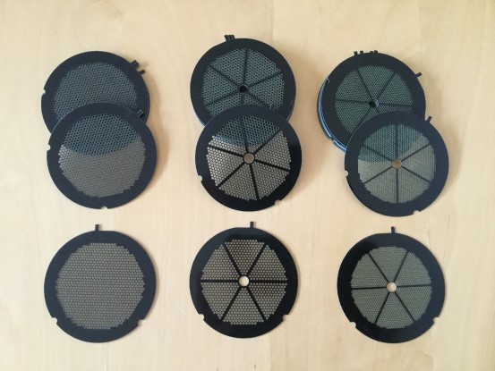
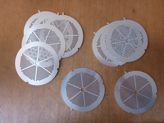
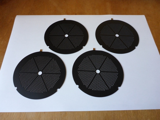
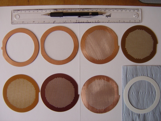
Ultra Thin Stators - in the making of a multi layered stator.
The stators on far right are ultra thin stators with extremely small holes, compared to the two sets on the left. These stators are so thin, they will be bonded to frames making a Multi-Layered Stator, MLS.
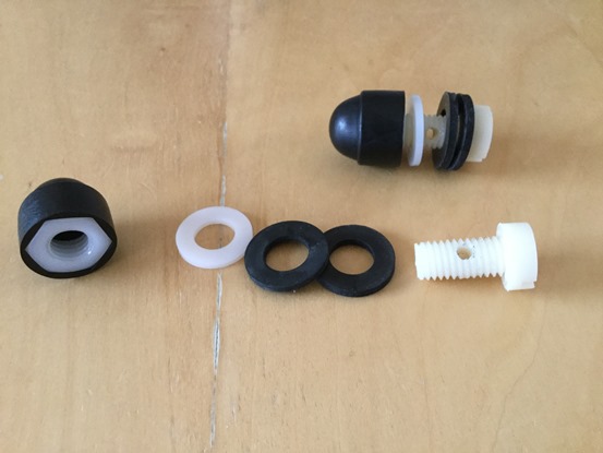
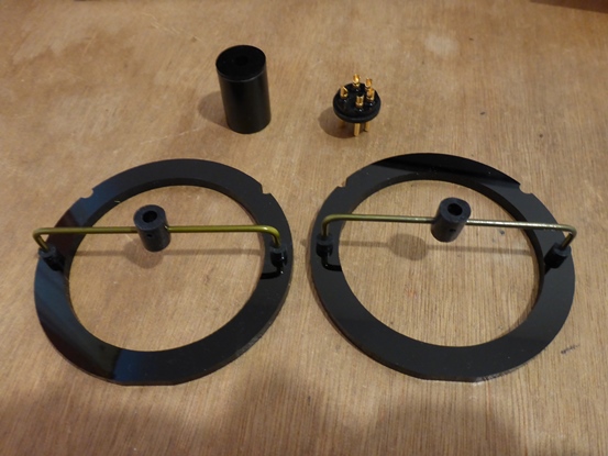
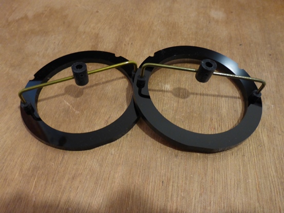
Lockable ear cup position for Spyder.
M10 Nylon nut and bolt, Nylon and Rubber washers, Cap for nut. A 3mm hole drilled through M10 bolt shaft for head band.
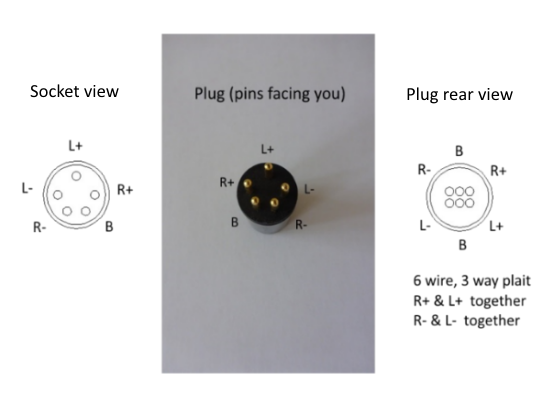
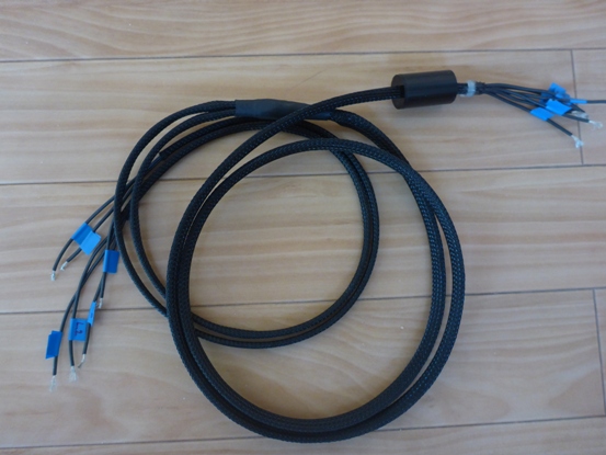
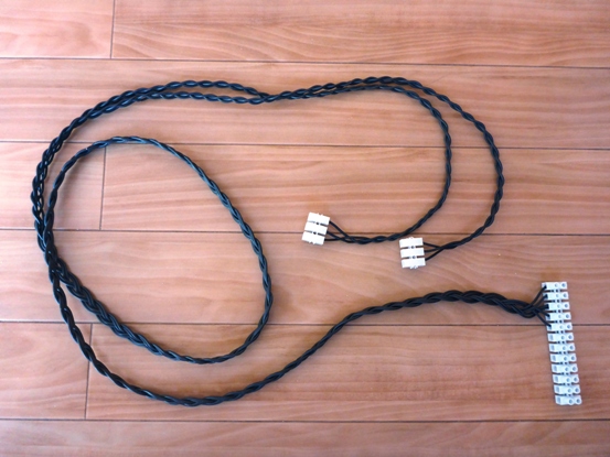
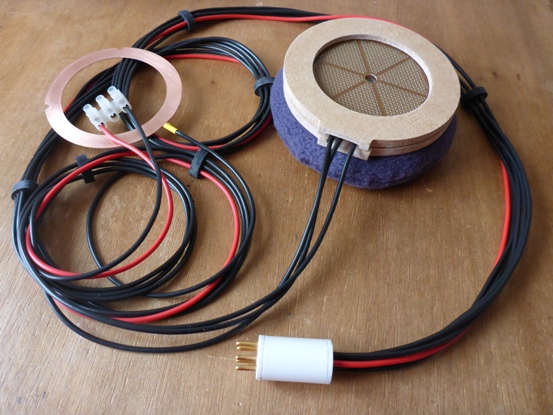
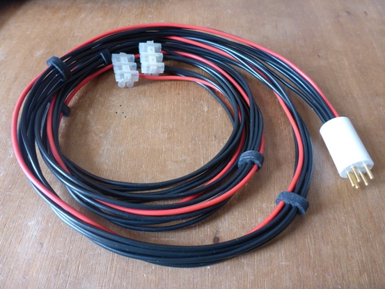
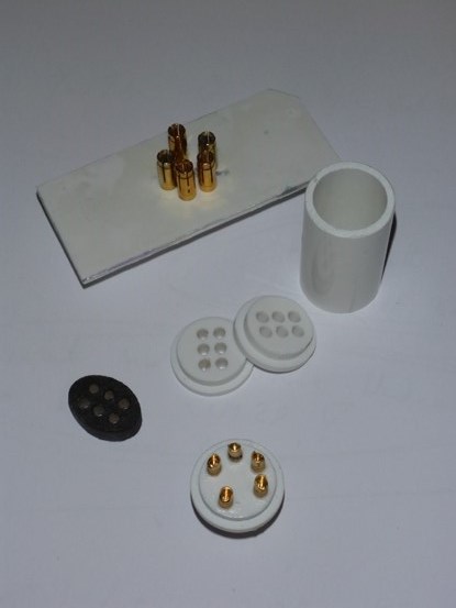
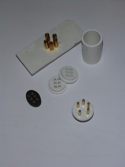
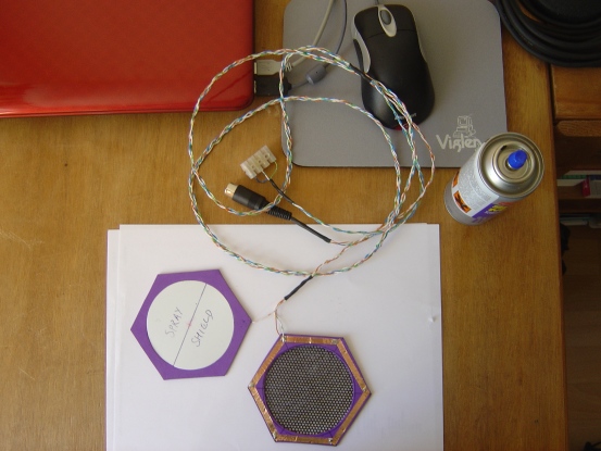
'Stax 5 pin pro' plug and Muamp 6 wire - 3 way plait details.
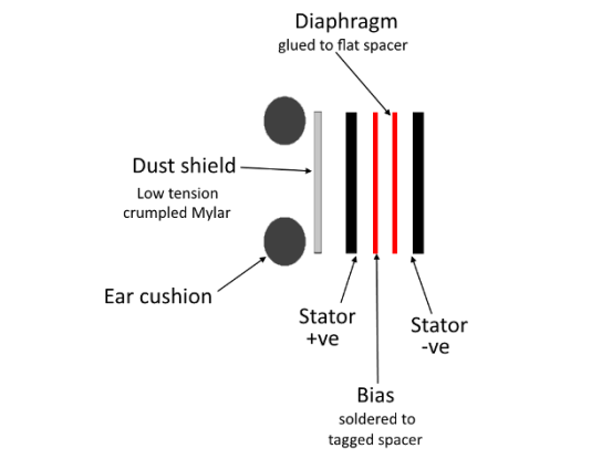
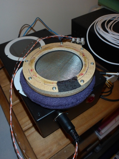
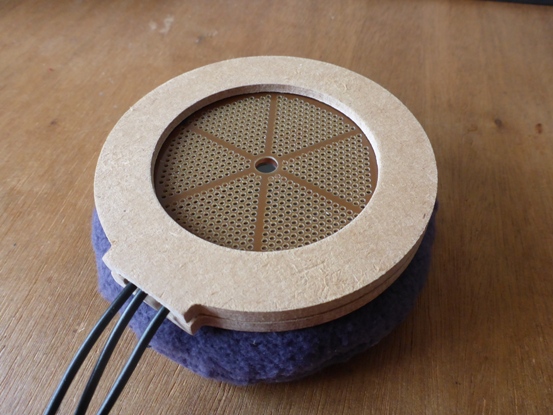
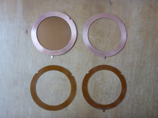
Electrostatic headphone panel construction.
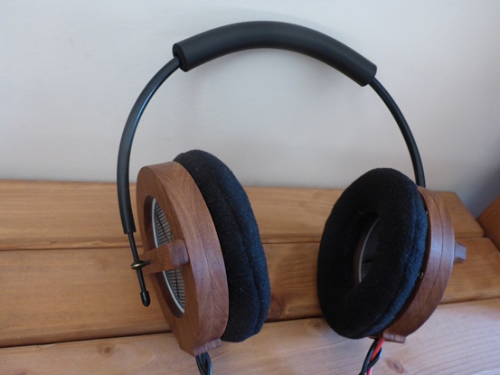
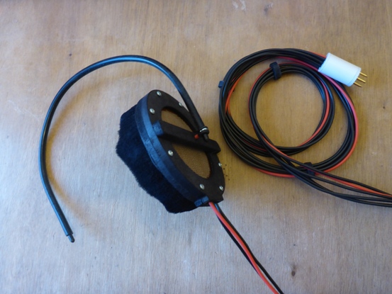
Neoprene tube headband cushion.
This neoprene tube cushion is from Sinclair & Rush (www.sinclair-rush.co.uk). I was trying to make a simple headband which is still comfortable. On the hardwood surrounds it does not provide enough padding to be comfortable. On the Muamp Spyder which is extremely light, it may be adequate...? I will test it on a Spyder after the next two Spyders are constructed.
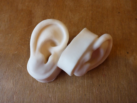
Silicon ears. These will form a part of my 'dummy head' headphone test jig, similar to a binaural head, but for testing headphones.
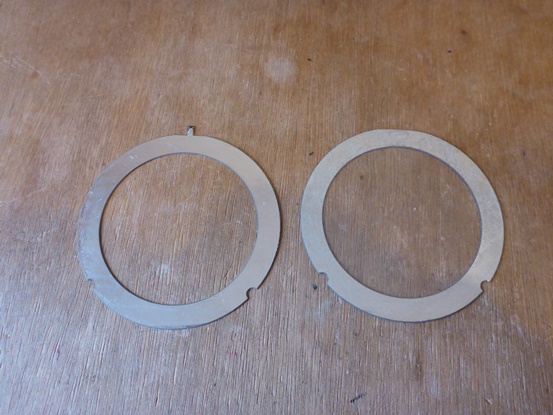
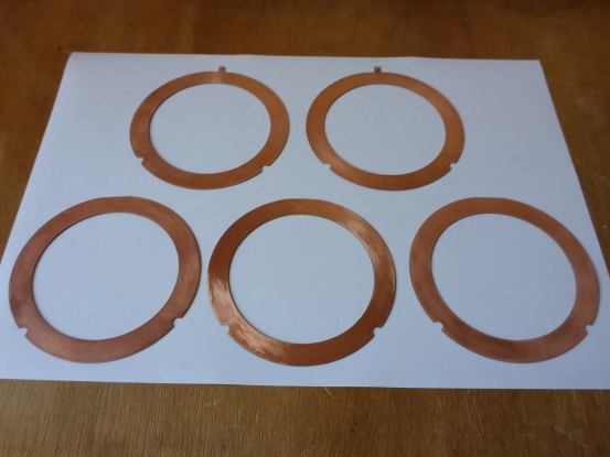
I was hoping to use these fabricated spacers for sale on the DIY page, but unfortunately they are not as good as I was expecting...
They are fabricated on HASL FR4 at 0.6mm thickness. The basic fibreglass board is 0.6mm, when the copper layer in on the board they measured 0.667mm on the micrometer. This is only 0.1mm thicker than the normal FR4 for Muamp spacers but it decreases the sensitivity of the finished panel considerably!
The HASL 'tinned' finish is not a problem, even though I would have preferred bare copper.
So the DIY spacers for sale on the DIY page are still the handmade version.
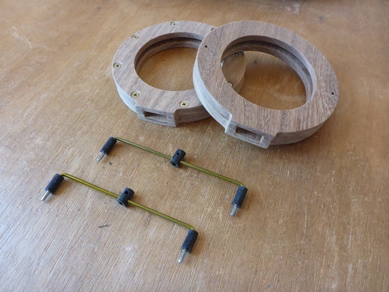
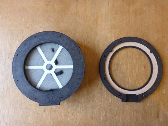
Muamp#6 ear cup brace and Perspex plug.
Muamp#6 Perspex ear cup brace.
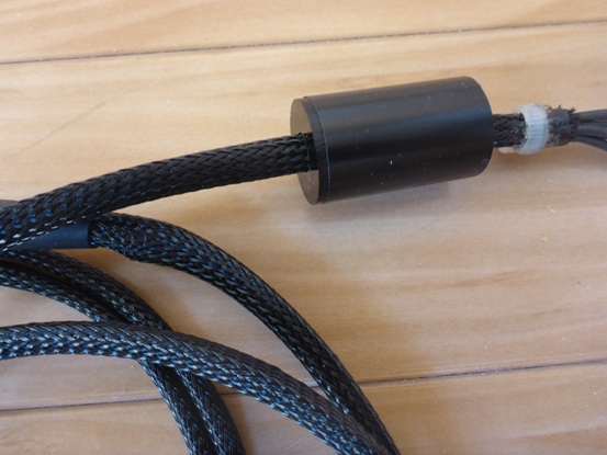
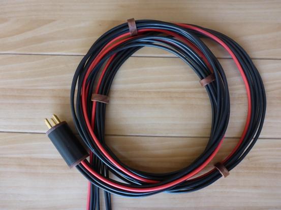
Close up of the headphone audiophile cable.
Muamp sheath cable. This style of cable is preferred by the headphone audiophiles.
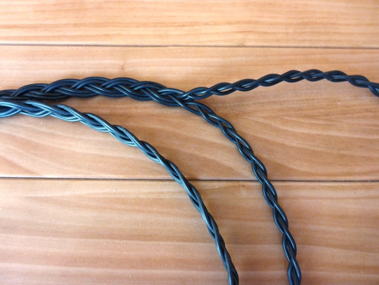
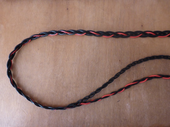
Close up of the new Muamp plaited cable.
This is an improved variation of the Muamp plaited cable. Thinner wire with greater insulation. Very light and flexible.
The original cable used on Muamp#1. It has separate conductors held with cable clips. Very low cable capacitance.
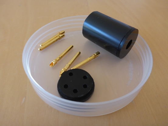
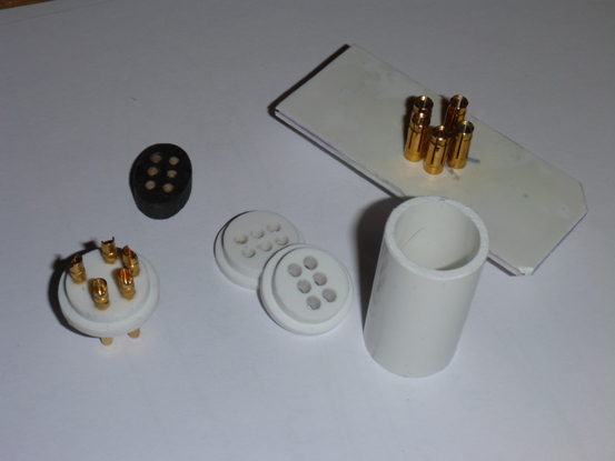
Muamp Perspex plug.
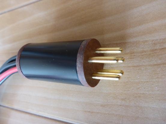
Hardwood end Muamp plug.
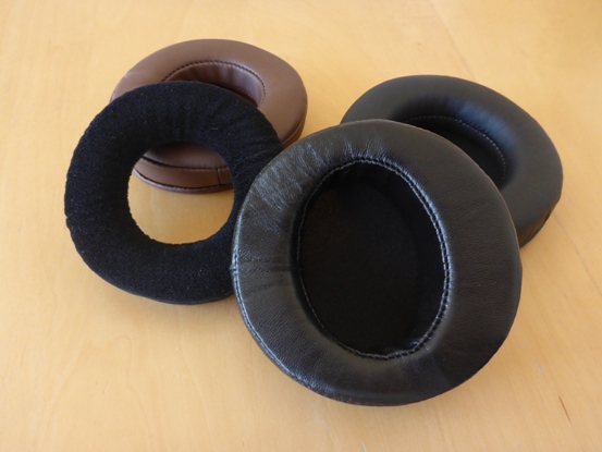
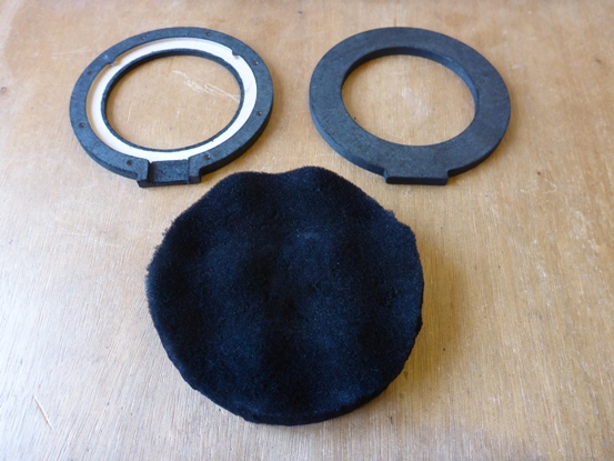
A range of Chinese bought-in ear cushions were tested to see if they would be suitable for Muamp ESHS. Large ear cushions made from synthetic materials to lambs leather were tested, but none could compete wth the comfort and breathablity of the Muamp fleece ear cushions. When listening to headphones for long periods, they must be comfortable and not make the ears sweat with build-up of condensation.

Muamp#4 photographed for a sales promotion.
Close up of the surrounds with ultra thin headband cross frame, just before inserting the electrostatic panels.
The customer of Muamp#5 requested an ultra thin cross frame to make the back as open as possible. Pleased to say he liked the result. The cross frame still allows the Muamp style headband, providing protection to the panel, but also provides extreme openness.
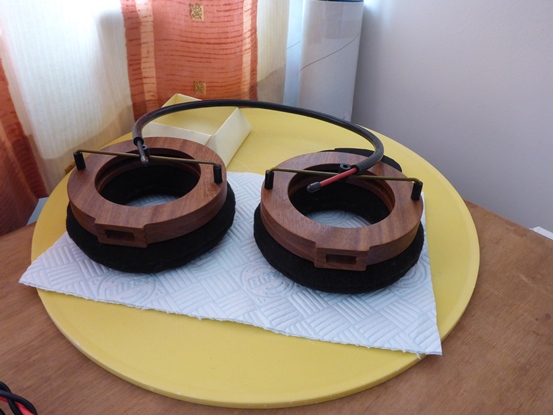
Final construction phase of Muamp#5.
Making Muamp#5 - custom made with ultra thin headband cross frame. Hardwood surround construction with the new style headband crossframe made of thin metal rod. Thinner and further away from the panel making it acoustically transparent.
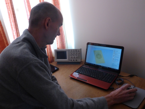
Me at the computer with Vectric CUT2D.
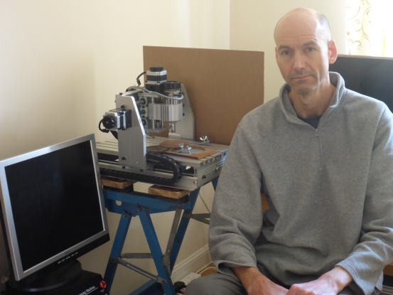
Me with my CNC.
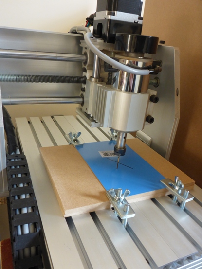
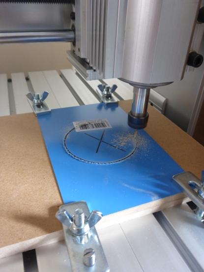
CNCing a set of spacers on ½mm Bungard single sided FR4.
Cutting inner.
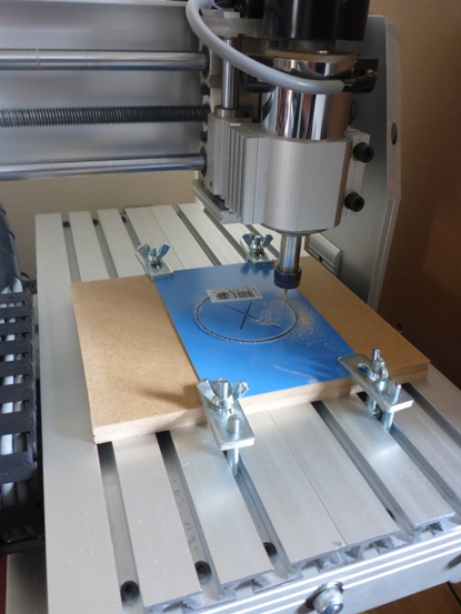
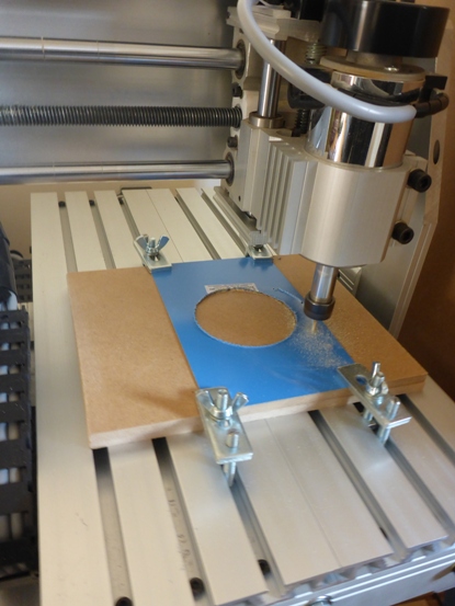
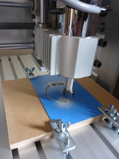
Now cutting outer edge.
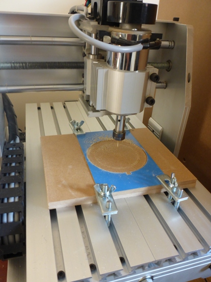
Cut complete. The multi-edge mill bit leaves a smooth finish.
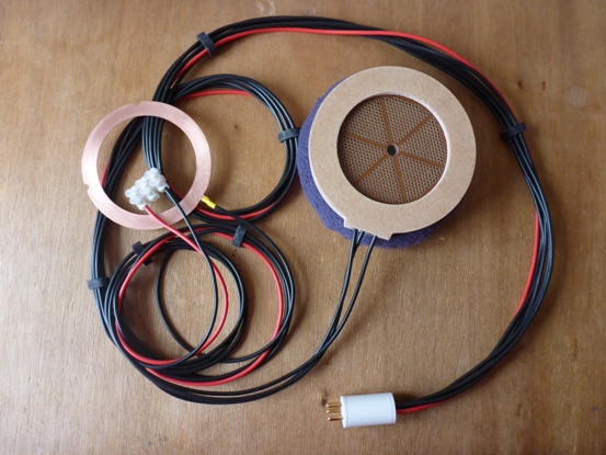
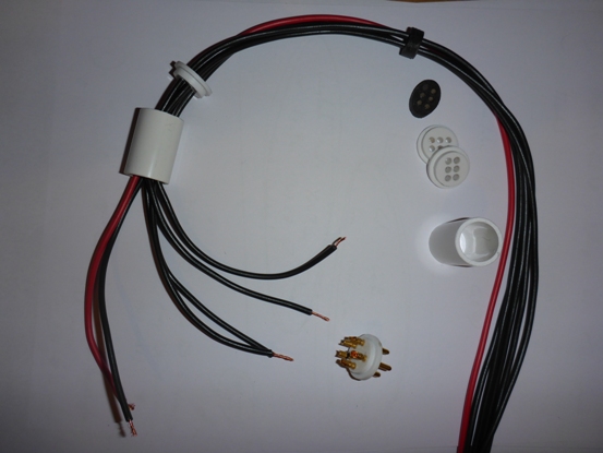
New style electrostatic headphone cable. Tidier than the last design and still ultra low capacitance.
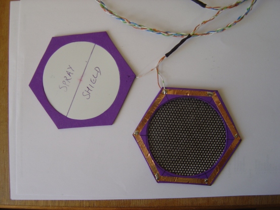
These are aluminium stators. PCB fabricated as 1mm aluminium sheet covered with a dielectric and then a copper layer. The copper side is tinned and sprayed with polyurethane clear Spray. Although these stator are the most rigid and should be the best out of all the stators I have made, they are not as flat as the Bungard stators. In future I will keep to CNC'ing my stators from Rapid Bungard FR4. Not only is it the flattest of all my stators, I can make them as I need them with changes I decide to make and not needing to write more Gerbers and then waiting for PCB production companies to send a batch in the post.
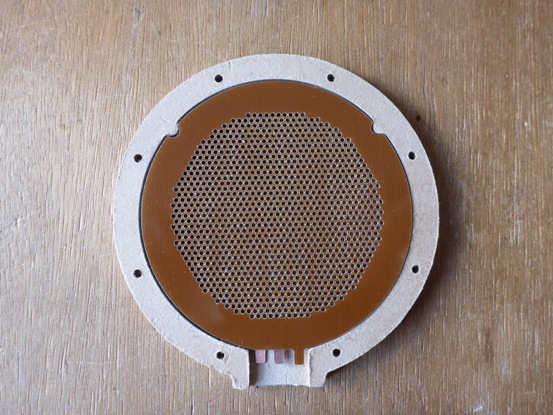
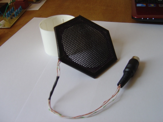
A test panel, the same as above, but using wire mesh outer dustcover.
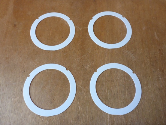
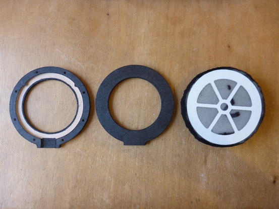
The stators, spacers and dustcovers used in the finished item.
Now we're getting somewhere!
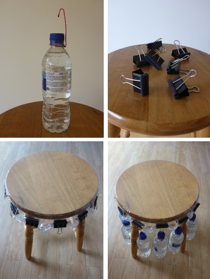
Various ways of tensioning the diaphragm; hanging weights,
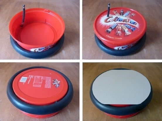
and tyre (inner tube) stretcher.
Mmmm..., Large panels completely covered in foam was not a good idea.
PCB (FR4) stators and MDF surround. Experimenting with different hole sizes and spacer thicknesses.
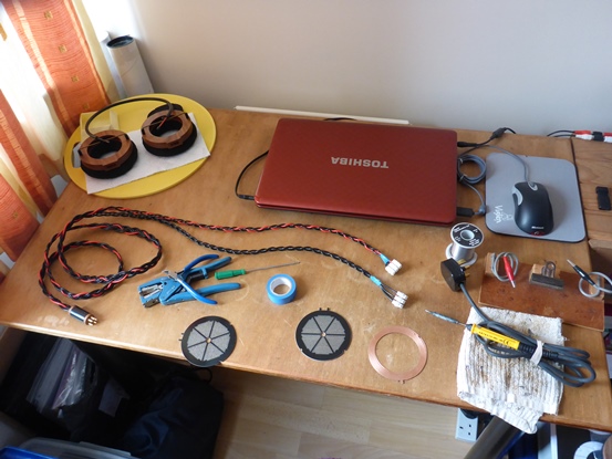
Making a Stax compatible cable.
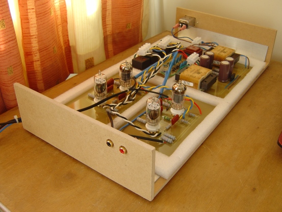
Semi-boxed and nearly ready for use.
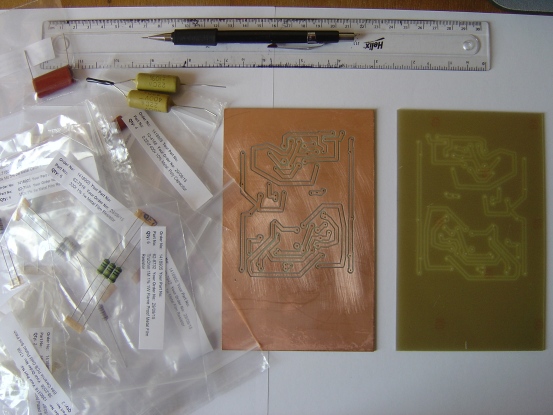
A CNC was used to cut the tracks and holes on this PCB for the energiser.
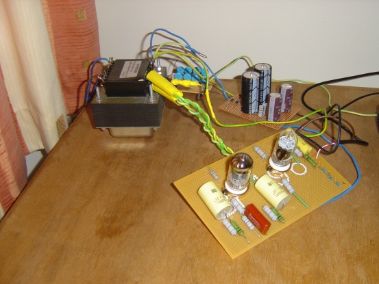
Early work on a valve energiser.
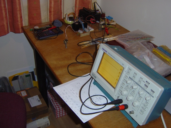
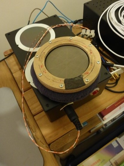
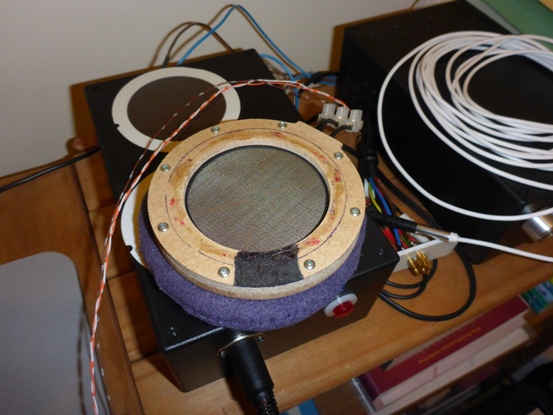
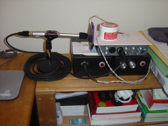
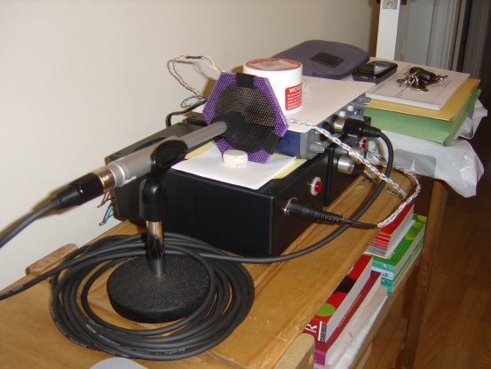
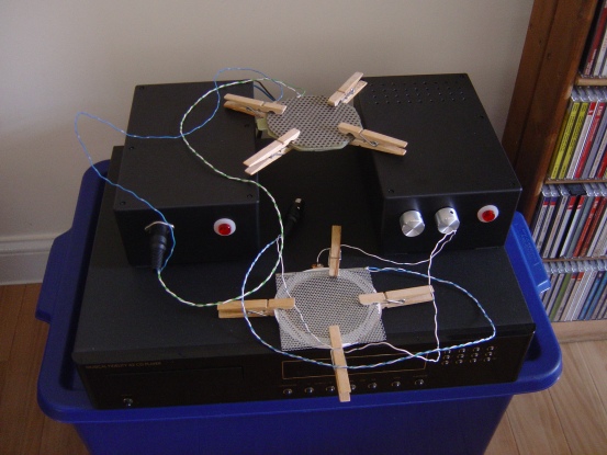
Testing panels with a 'measurement condensor' microphone.
Various test panels with 304 stainless steel and thin neoprene spacers.....
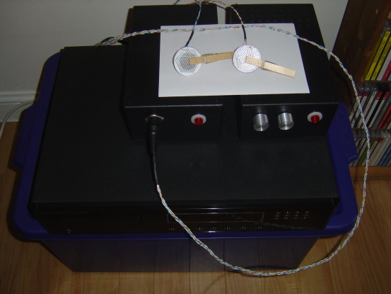
Testing small 'On ear' panels.
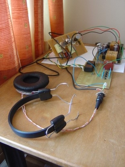
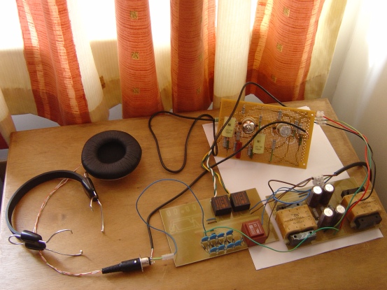
My first energiser (transformer type) testing another early panel. In this one I have replaced the plastic spacers with FR4.
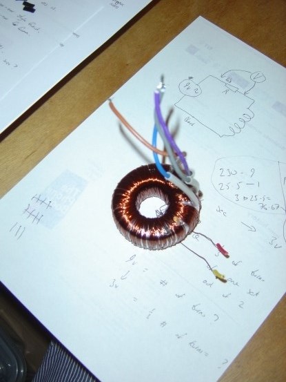
Home wound audio toroidals are not easy to wind.
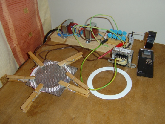
My very first panel. Using two pieces of perforated 304 stainless steel. It uses a basic transformer energiser and isolated mains step-up for the bias.
For a simple panel, it has amazingly good sound.
The Muamp transformer energiser circuit diagram and construction information can be seen on the "uAmp-energiser" page.